The DigitGrid
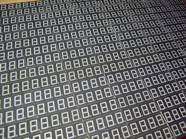
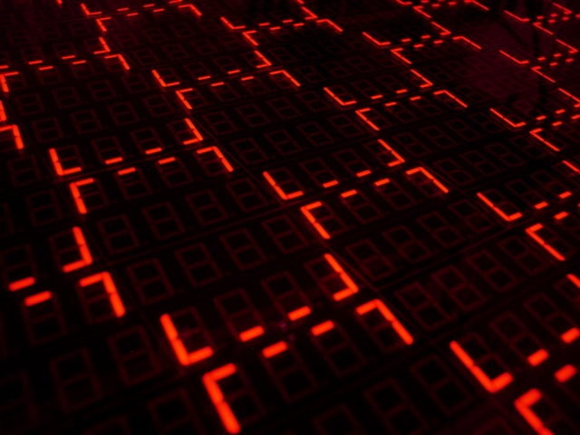
The DigitGrid is a new type of display. Typically used to display numbers, seven segment displays have been around in various forms for over 100 years. The typeface of the numbers is determined by the layout of the display. However when you take a large number of off-the-shelf displays and put them together you can display a lot more than numbers…
The making of the DigitGrid
The DigitGrid is an array of seven-segment displays. There are 4096 LEDs, forming 512 7-segment digits (they are actually 8 leds each if you count the decimal point). Every 16 digits is grouped together into a “module” with a Texas Instruments TLC5920 LED Driver/Controller. Each module has it’s own PCB with input and output headers. The modules connect together end-to-end to form rows of 32 x 2 digits. There are 8 of these rows. All of the rows are controlled by a Spartan 3E FPGA that also receives frames over serial. The various animations are written in Processing and then sent out frame by frame to the FPGA over 230kbps serial. The TLC5920 has a current limiting setting and as a result, the whole display draws less than 1 amp.
At some point while I was in school it became clear that the only way to satisfy my intrigue with 7-segment displays would be to build a massive grid of them. I had seen controller ICs such as the Maxim MAX6955, but the $10 ea. price tag (or $30 ea on Newark, WTF?) quickly made the project seem too expensive. Later during finals I found the TLC5920 at less than $3 ea! It was tough to resist the urge to start the project during finals.
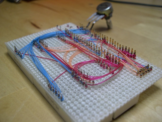
I wasn’t able to find much information on the TLC5920 besides the datasheet, so I ordered 2 and hand wired them up to some common cathode 4-digit 7-segment displays I had.
Wire wrapping and perfboard is an ancient technique, but it turns out it’s pretty fast and easier to rework than soldering. Radioshack actually carries wire wrap tools!
Once the design was mostly proven, I used Eagle to make up some PCBs and had Seeed Studio make them.
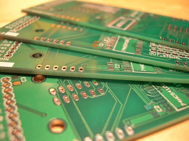
The first rev of the circuit boards for the LED modules have arrived!
It’s rare that the first rev of PCBs will work perfectly, and this was no exception. I completely missed one connection on the TLC5920. I wasn’t sure if the signal would need buffering as it was passed between modules so I included a pad for a 74xx541 octal buffer. I didn’t need this. The other challenge is that the TLC5920 only comes in 48pin TTSOP surface mount.. these are VERY small pins! After some frustrating erratic behavior from the ‘5920 I realized I was getting them way too hot when soldering. It was very satisfying to see the first PCB soldered together and working!
Soldered together the first module. After some testing, and 1 green wire fix, it works!
Getting the module to light up is just the beginning. I still have to send data to it, and it needs to pass that data on to it’s neighbor. I wired up a PIC microcontroller on a breadboard and worked on chaining a couple modules together.
Each module needs to pass on serial data to the next in bucket-brigade style. I soldered together a few modules to test. Look for cameo appearances by the Saleae Logic analyzer and the Dangerous Prototypes Bus Pirate!
Things were working great with two modules, but then when I started chaining more together, I started loosing data. This was a problem in software luckily. Even with the dropped bytes, I was excited enough to take some pictures. A used IKEA Norden table makes a great desk.
Chaining together multiple modules works! However, the software needs work; i’m losing some bytes here.
Getting the endianness of the data backwards produced a pretty cool looking alien display. However, with the correct order I can sent regular characters OR alien display if I want.
Still working on the software. I think the byte order is wrong here. Looks cool though!
It is way cheaper to make a lot of small circuit boards then a few large ones. The charges are based on sq. in. and there are huge quantity discounts. I thought I was onto something by taking advantage of this to create a modular display. However, now I had to buy and solder interconnects between the modules. Those little 0.1″ connector pieces really start to add up.
All of the modules connect end to end with these headers. If you want to be cool, use blue wires for your green wire fixes. When I worked at Apple I loved seeing a proto iMac motherboard filled with little green wires.
Once I was convinced I had the correct circuit for the modules I made a new simpler PCB and had a bunch of them made. I also designed and ordered PCBs for a PIC16F648 microcontroller to attach to the end of each row. My idea was that I would daisy chain serial to each microcontroller for each row. You can tell from the dates on the PCBs I’ve been working on this project for a while! Waiting 30 days for boards to arrive doesn’t help.
The top board is rev 2 of the module board; corrected and simplified. The bottom is the first rev of the row controller boards.
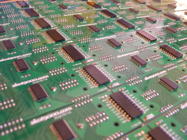
Now that I had the final module PCBs and a ton of parts from Mouser and Jameco I had a lot of soldering to do. A while back my friend Boris changed my life by giving me a rebuilt Metcal STSS-001 soldering station. I can never go back to using those cheapo fire starter soldering “irons” again. Seriously if you are going to solder more than a couple joints, invest in a decent soldering station. It makes the job much easier, faster and better. Oh yeah, get some good fine solder and a lot of liquid flux!
Everything is soldered. This represents a LOT of hand soldering!
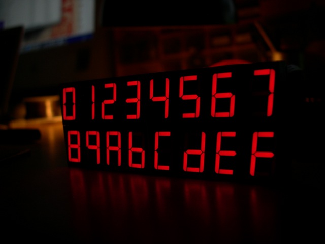
When the whole thing was soldered together and lit up, all I could do was stare at it. It’s so beautiful. Justin has this story about a Swedish friend of his who had a printer that wouldn’t stop printing the letter ‘F’. In the story Justin’s friend says “There was so much letter F!” in an amazing accent. This test was in honor of that story.
All of the boards are connected and working with a simple test. “So much letter F!”
So by now I had taken and throughly enjoyed CS150 Digital Design at UC Berkeley, which was taught on Xilinx FPGAs. It became clear that I could use one FPGA and replace all of my row controllers, as well as have much faster serial communication. One of my classmates sold me a Digilent Nexys 2 (Spartan 3E, 1200k gates) dev board and I got to work on writing some Verilog to control my display. This ended up being a much better solution. Writing Verilog requires me to concentrate on it for hours on end without interruption.. Even a small interruption causes me to completely forget what I’m doing. Also, The Xilinx ISE development environment requires Windows, which just isn’t a happy place. If they made the software for Mac, I don’t think i’d ever come out of my hardware description language hole.
I have decided to not use individual row controllers, and instead use a single FPGA for the whole grid. Here is a proto wiring harness.
The project needed to graduate from a pile of wires and circuit boards on my desk. I mounted all of the modules on some clear polycarbonate from TAP (Austin was very adamant that I use polycarbonate and not acrylic. Acrylic is a pain to drill) I mounted the FPGA, wiring harness and power supplies on the back of the plastic. Some aluminum channel was used to make a wall mount. The whole project got completely off my desk and onto the wall. The hardware is pretty much done, and now it’s all about perfecting the software.
Here is the backside with the finalized wiring harness, FPGA controller, wall hang mount, and power supplies.
Wiring harnesses are always the hidden problem in projects. They are expensive to do right and almost always time consuming. When I was in EE192 we had these cool IDC/IDT punch down connectors, but the tool to do the punching was $300 (!@#$!!!)!!! I guess after seeing the pro $300 tool, I somehow thought the little plastic T tool for $25 was a good deal. While it works great, why is it $25? If I ever lose this one I’m going to make one out of an old butter knife and a file in about 10 minutes. Seriously, AMP/TYCO and/or Jameco this thing is a ripoff.
Close up of the final wiring harness. These punch-down connectors really saved me a lot of time, but not money!
I got the 4-digit 7-segment modules from a guy on ebay in Thailand. He was nice and would setup an auction for whatever number of them I wanted. I wish I could get them at his price however. In the future when I make more of these panels, I’m going to need to find a really good price.
Here is the frontside; A Sea of Segments! A piece of red plastic goes over the front to decrease the contrast of the unlit segments.
A piece of translucent red plastic (acrylic this time, no drilling) over the front of the segments decreases the contrast of the unlit segments, so you can only really see the lit segments. It’s a nice effect. Almost any alarm clock that has LED segments will have this.I took a display module to TAP and tried it with various tints. Also, taking pictures of my display in focus is a challenge!
A test of the FPGA showing a unique pattern; 512 digits of π
Optimizations in my Processing code, and in the Verilog code allowed me to get very smooth motion over a 230kbps serial connection to the display. This works out well for one panel, but I’m going to need more bandwidth when this panel gets bigger. I’m thinking DVI may be the way to go.
One of the design questions I tossed around in the beginning was whether I want the LEDs to be dimmable or not. The TLC5920 doesn’t have any individual dimming function. It would look amazing, but would require something like twice the amount of data for the same number of digits. I think I’ll try and expand the display to more digits before I attempt anything with dimming.
A test to see how high I could get the frame rate. at 230k baud serial, I can get very smooth motion. Unfortunately the digits are not dimmable; that is from the camera.
This thing is cool.
Taking worthy pictures of the display has been one of the more difficult things. I have dozens of lame, out of focus pictures— but trust me, it always looks cool in person.
Playing around with camera settings.
Well, thanks for looking. Future improvements are going to include; more digits! I’d also like to work on computer-free playback of animations from a SD card, that would be more appropriate for a gallery. I have a couple interactive modes, but I will be expanding those in the future too.
**Files
**schematic – second revision schematic of the module PCB
layout – second revision PCB layout of the module PCB
pi_fill – example processing sketch that sends 512 digits of pi

